|
7 |
|
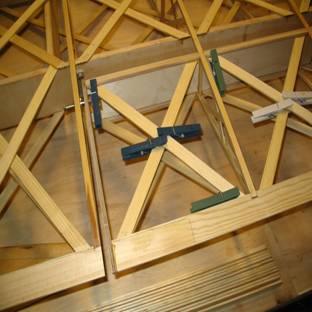
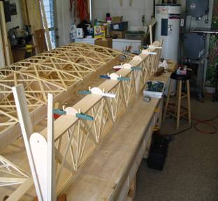
With the small spar caps now glued in, geodetic bracing can be added to give the aileron stiffness and strength. Each geodetic strip is glued to the underside of the spar cap and into a groove cut into the inside face of the trailing edge. Where the geodetic strips cross each other, they are glued together. The resulting structure is both stiff and lightweight. Clothespins are used as clamps. Their modest clamping pressure does not squeeze the epoxy glue out of the joint.
Also in this picture can be seen the hinge bolt, which passes through a bellcrank bearing and into the aileron endplate. |
|
The aileron can now be cut free of the wing by sawing through the ribs between the aileron spar and the rear spar of the wing. The aileron is provided with rounded nose pieces to be wrapped with leading edge plywood in the same way as the wing. |
|
Here, the aileron, now free of the wing, is supported on its trailing edge by a couple of handscrews, padded with scrap wood. The stumps of the rib capstrips can be seen where the clothespins are clamping the rounded nose-pieces to the leading edge of the aileron spar. The aileron well of the wing can be seen behind the aileron, now devoid of the aft end of all the ribs.
When the aileron endplates were positioned on the ends of the aileron, one of the nose-pieces was used to locate the leading edge curve of the endplate perfectly congruent with the curve of the nose pieces. |
|
Thin plywood is glued around the leading edge of the wing. First the plywood is glued and stapled to the underside of the wing. When the glue has set up, the plywood is bent around the nose pieces, held in place with shock cord, then glued and stapled to the upper surface of the leading edge. |